Frequency modulation is widely used, particularly on frequencies above 30 MHz. It offers many advantages, particularly in mobile radio applications where its resistance to fading and interference is a great advantage. It is also widely used for broadcasting on VHF frequencies where it is able to provide a medium for high quality audio transmissions.
In view of its widespread use, scanners and many other receivers are able to demodulate these transmissions. Naturally there are specifications and figures that receiver manufacturers quote for the performance of their sets when receiving FM.
What is FM?
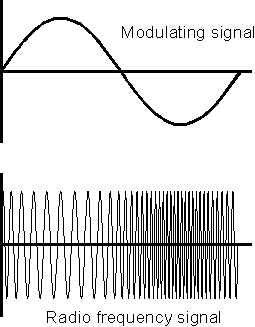
As the name suggests frequency modulation uses
changes in frequency to carry the sound or other information that is
required to be placed onto the carrier. As shown in Figure 1 it can be
seen that as the modulating or base band signal voltage varies, so the
frequency of the signal changes in line with it. This type of modulation
brings several advantages with it. The first is associated with
interference reduction. Much interference appears in the form of amplitude
variations and it is quite easy to make FM receivers insensitive to
amplitude variations and accordingly this brings about a reduction in the
levels of interference. In a similar way fading and other strength
variations in the signal have little effect. This can be particularly
useful for mobile applications where charges in location as the vehicle
moves can bring about significant signal strength changes. A further
advantage of FM is that the RF amplifiers in transmitters do not need to
be linear. When using amplitude modulation or its derivatives, any
amplifier after the modulator must be linear otherwise distortion is
introduced. For FM more efficient class C amplifiers may be used as the
level of the signal remains constant and only the frequency varies.

Figure 1 Frequency modulating a signal
Wide band and Narrow band
When a signal is frequency modulated,
the carrier shifts in frequency in line with the modulation. This is
called the deviation. In the same way that the modulation level can be
varied for an amplitude modulated signal, the same is true for a frequency
modulated one, although there is not a maximum or 100% modulation level as
in the case of AM.
The level of modulation is governed by a number of factors. The bandwidth that is available is one. It is also found that signals with a large deviation are able to support higher quality transmissions although they naturally occupy a greater bandwidth. As a result of these conflicting requirements different levels of deviation are used according to the application that is used.
Those with low levels of deviation are called narrow band frequency modulation (NBFM) and typically levels of +/- 3 kHz or more are used dependent upon the bandwidth available. Generally NBFM is used for point to point communications. Much higher levels of deviation are used for broadcasting. This is called wide band FM (WBFM) and for broadcasting deviation of +/- 75 kHz is used.
To receive FM a scanner may have two different modes, one labelled WBFM and the other NBFM. The correct mode must obviously be selected for correct reception. Also if it is anticipated that reception of both modes is required, then the receiver must have the capability of receiving both of them.
Receiving FM
In order to be able to receive FM a receiver must
be sensitive to the frequency variations of the incoming signals. As
already mentioned these may be wide or narrow band. However the set is
made insensitive to the amplitude variations. This is achieved by having a
high gain IF amplifier. Here the signals are amplified to such a degree
that the amplifier runs into limiting. In this way any amplitude
variations are removed.
To convert the radio frequency signals appearing at the output of the IF stages of the receiver into audio voltage variations to be amplified by an audio amplifier an FM demodulator must be used. This converts the frequency variations of the carrier into audio voltage variations. This is done using a circuit where the output voltage is dependent upon the input frequency. The linearity of the response is obviously important otherwise distortion is introduced. A number of circuits can be used to do this. Two popular circuits that use discrete components are the ratio detector and the Foster-Seeley detector although today FM demodulators are contained within integrated circuits and the only requirement is for a coil and capacitor to connected to the chip to provide the frequency dependent circuit.
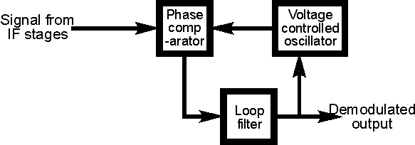
Another method is to use a phase locked loop. The way in which this circuit operates to demodulate FM is very simple. The circuit is set up to operate as shown in Figure 2. The FM signal from the IF stages of the set is connected to one of the phase detector inputs as shown, and the output from the VCO is connected to the other.

Figure 2 A phase locked loop FM demodulator
With no modulation applied and the carrier in the centre position of the pass-band the voltage on the tune line to the VCO is set to the mid position. However if the carrier deviates in frequency, the loop will try to keep the loop in lock. For this to happen the VCO frequency must follow the incoming signal, and for this to occur the tune line voltage must vary. Monitoring the tune line shows that the variations in voltage correspond to the modulation applied to the signal. By amplifying the variations in voltage on the tune line it is possible to generate the demodulated signal.
Squelch
When a receiver switched to FM and no signal is present
it is found that high levels of audio noise are heard. This is very
unpleasant and to overcome this most receivers have what is called a
squelch circuit. This cuts off the audio when no signal is present. Many
scanners and hand-held VHF or UHF transceivers have a control to adjust
the signal level below which the audio cuts off. By using this control,
the set can be adjusted to detect very low level signals if necessary.
Quieting specification
One of the advantages of FM is its
resilience to noise. This is one of the main reasons why it is used for
high quality audio broadcasts. However when no signal is present, a high
noise level is present at the output of the receiver. If a low level FM
signal is introduced and its level slowly increased it will be found that
the noise level reduces. From this the quieting level can be deduced. It
is the reduction in noise level expressed in decibels when a signal of a
given strength is introduced to the input of the set. Typically a
broadcast tuner should give a quieting level of 30 dB for an input level
of around a microvolt.
Capture effect
Another effect that is often associated with FM
is called the capture effect. This can be demonstrated when two signals
are present on the same frequency. When this occurs it is found that only
the stronger signal will heard at the output This can be compared to AM
where a mixture of the two signals is heard, along with a heterodyne if
there is a frequency difference.
A capture ratio is often defined in receiver specifications. It is the ratio between the wanted and unwanted signal to give a certain reduction in level of the unwanted signal at the output. Normally a reduction of the unwanted signal of 30 dB is used. To give an example of this the capture ratio may be 2 dB for a typical tuner to give a reduction of 30 dB in the unwanted signal. In other words if the wanted signal is only 2 dB stronger than the unwanted one, the audio level of the unwanted one will be suppressed by 30 dB.
Summary
FM is widely heard on frequencies above 30 MHz where it
is the most widely used mode for voice transmissions for point to point
radio. Below 30 MHz it is rarely used although some radio amateurs can be
heard at the top end of the ten metre band on FM. In view of its
widespread use above 30 MHz it is an essential mode for any scanner or
other wide band receiver.